Biasing a Common Emitter Transistor
The voltage divider method
There are various ways to bias a transistor but after watching several youtube videos this seems to be the recommended way for best transistor stability - a voltage divider bias on the base. This tutorial is dealing with just small signal models at low voltages. It is assuming you have an idea of what operating (idling or quiescent) current will be going through the collector. If you have no idea then enter not more than half of the maximum current rated on the transistor's data sheet. Change the following suggested values as needed and then click Calculate.
RE =
R2 =
R1 =
RC =
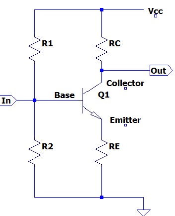
Image created from LTspice app Here
Explanation
1. The emitter resistor RE is calculated first by figuring 10% of the supply voltage and dividing that by the quiescent collector current. Voltage divided by current equals resistance. Ohms law. Putting a resistor on the emitter is part of stabilizing the transistor from thermal run-away.
RE = (.1 * Vcc) / Icq
2. R2 is figured next. It's voltage is the voltage of RE (since they are in parallel) plus the voltage drop of the transistor which is approximately .6 to .7 volts. The current is figured by taking the collector current divided by the gain of the transistor (ß) and then taking that figure times 10. The purpose of taking it times 10 is to have a strong current (stiff) flowing through the voltage divider of R1 and R2 to keep the circuit of the transistor stable. Use ohms law to figure the value of the resistor since you now have the voltage and the current.
R2 = (VRE + .65) / (10 * (Icq/ß))
3. The voltage of R1 is the supply voltage minus R2 voltage. Finding the current is similar to R2 except instead of taking it times 10 you take it times 11 because it carries the current flowing through R1 plus the required current through the base to bring the transistor to quiescence. This current is the collector quiescent current divided by the gain of the transistor (ß).
R1 = (Vcc - VR2) / (11 * (Icq/ß))
4. The collector voltage is figured by subtracting the voltage of the emitter resistor from the supply voltage and then taking half of that. The other half is across the collector emitter of the transistor. You already know the current you want flowing through the collector (Icq) so now you can figure its value in ohms by using ohms law.
RC = ((Vcc-VRE) / 2) / Icq
5. This circuit is the basic DC bias diagram without the capacitors. In an actual working circuit capacitors will be necessary between the input signal source and this circuit, between the output of this circuit and the next stage or load and usually a bypass capacitor across the emitter resistor.
6. Here's an excellent video explanation on YouTube from MONTV Homebrewing Click here